Processing Technology And Optimization Of Cnc Machining Center For Special-Shaped Solid Wood Furniture Parts
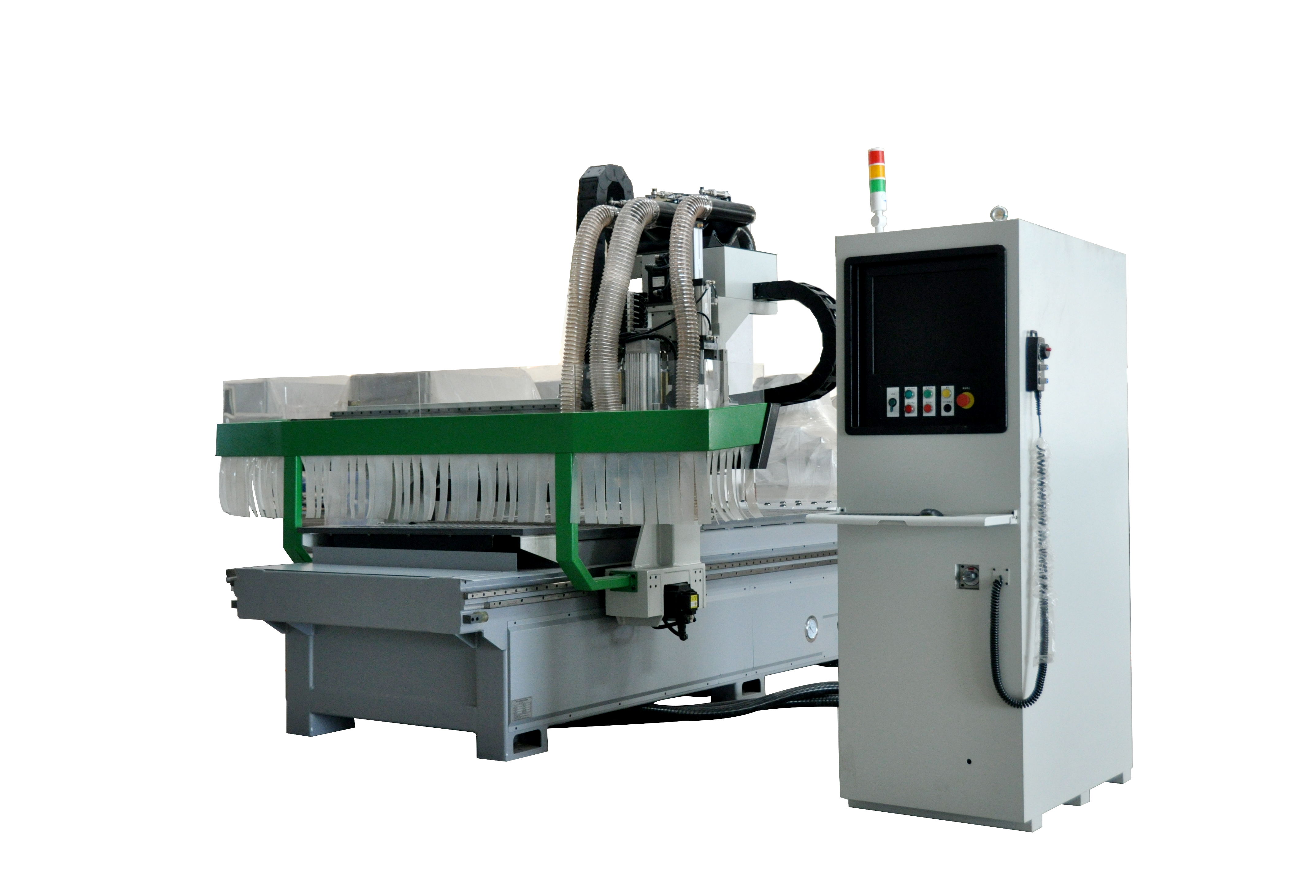
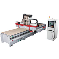
Furniture Manufacturing CNC Center
There are three reasons for the actual production problems often encountered in the processing route is not easy to control, tool path editing complex this phenomenon: one is the base of solid wood furniture shaped parts processing for plate materials, there are some errors in the size and thickness; two is a variety of machining tool, parameter adjustment is relatively complex; the three is to adjust the error of CNC machining center tool.
I think we can solve this problem by optimizing the design method of the drawing and determining the tool path by selecting the right tool and adjusting the tool parameters. An example of the machining of the top line of the European type bed is taken as an example. The specific operation method is expounded and the validity of this method is verified.
Software based parts drawing and tailored drawing optimization design, CNC machining center usually comes with a software system with certain drawing ability. When dealing with some complicated graphics, general software needs to draw support from other drawing softwares, such as AotoCAD, Rhino and so on. In the case of European bed top line modeling complex, mobile location in the software system can only be simple, the tool path design, all kinds of tool path path cannot be drawn in the software, can only be drawn by AutoCAD on road, and then edit parameters in software.
After determining the design scheme, it is necessary to draw a part drawing with three views as the basis for the expression. In the CNC machining center, the selection of the main view direction should reflect the shape characteristics of the parts.
After the completion of parts drawing can carry on the production scheduling, the simulation of substrate specifications format in the software, will move to the base part drawing wide selection, cutting form.Taking into account the utilization of materials, some complex, irregular shapes are often decomposed and assembled at last. In case of the case, the top line of the European type head is complex. If the whole processing is carried out, the base material with the specification of 2440mmx1220mm can only be processed 2. In this case, the complete top line of the bed is planned to be decomposed into 6 sections to be processed, which can increase the utilization ratio of the material. As the shape of the top line of the bed is symmetrical, only three sections of editors are needed to edit the knife path, and then the tool path is mirrored.
Cutting board diagram on the substrate In the actual machining process of the CNC machining center, the path of the tool changes according to the original part drawing, that is, the offset command provided in the software is a new graphic generated according to the original part drawing. When using this command on a continuous curve, there will be no problem, but when decomposing a continuous curve into segments, the way of decomposition will have a greater impact on the machining accuracy. In the part curve decomposition, should try to choose the curve slope changes smaller parts, preferably in the same position of the slope.In the case, the decomposition of the two components is used.Practice has proved that in the small changes in the slope of parts of the decomposition of parts processed together recombination effect to the selected S Table 1 processing tool in inch) due to changes in the endpoint slope, even in the same part of the same curve, After breaking down into two different parts, the slope of the endpoint changes with the trend of the curve, that is, the slope of the two points may be different after being decomposed. After the path editing, the error will be further enlarged and the processed Parts can not be docked, the two components of the mismatch tool path optimization and design tool path editing complete graphical decomposition, you can drawing on the graphics processing design. The so-called processing map refers to the software in accordance with the shape of the parts to draw a series of graphics to reflect the tool path (tool path), but also through the computer simulation software to achieve a graphics. There are many factors that need to be taken into consideration in the process of drawing the drawing. The typical path with the tool axis, the shape of the tool, the processing sequence of the tool, the depth of the tool processing and the access point position of the tool etc. The general steps of using software to process the drawing design as follows:Machining tool selection. Machining center tool selection is completed in the state of human-computer interaction, which generally require the operator of all types of tools are quite familiar with the properties in order to be able to select according to product modeling features and scheduling of the appropriate choice of processing tools. CNC machining centers generally require cutting tool used at the bottom cutting function, and with guide wheel or vertical cutting function can not be used. However, some tools with guide wheels can still be used after simple processing. Such tools can not cut the material vertically. In machining, you can use the tool with clear-bottom function to guide it, which can make it smoothly vertical to the machining datum, and then the corresponding cutting feed. Case, according to product modeling features and scheduling diagram, chose five kinds of processing tools.It should be pointed out that two cases with guide wheels were chosen for the case. In production, the guide wheels of these two tools affect the machining of the workpieces, so that their guide wheels are ground off to make them a tool that does not have vertical cutting and does not have a guide function.
Processing depth adjustment. Adjustment accuracy error (usually l ~ 3mm) and the thickness of the plate thickness error will be superimposed in this process, making the adjustment of the depth of the process become complicated and difficult to control. Knife on the processing depth of the relatively high requirements. The processing depth is too large, it will easily lead to material chipping, and will result in excessive cutting force caused by material displacement, irreversible damage to the material; processing depth is too small, the number of cutting tool increases, the processing efficiency is low . Therefore, the appropriate depth of processing is an important guarantee of high efficiency and qualified parts. Case, due to the diameter of the inch knife is relatively large, a cut of the material damage is serious, in view of this situation, and ultimately by 3 cutting to achieve the desired results.
The selection of processing order. Has an important influence on machining sequence of the processing quality of the workpiece, the processing sequence of the adjustment, the need to consider the cutting amount and tool diameter, shape and other product features and other factors. In the case, according to the characteristics of the products, the processing order is preferred: clear bottom knife, round bottom knife, round knife. It has been proved by practice that the rate of finished products is the highest in this process. The frequent loading and unloading tools in machining will also affect the machining accuracy. We should try to minimize the number of tool changing, so as to avoid efficiency reduction and error amplification during tool changing.
Tool path optimization. The adjustment of the path of the import and export of the knife is a step that can not be ignored. The general CNC processing center software has the function of adjusting the path of entering and leaving the knife. Because the cutting edge of the type cutter is not on the same vertical line, sometimes the diameter of the lower end cutting edge is larger than the upper end. If the cutter receiving procedure is executed directly at the initial cutting point and the cutter receiving point, it will cause damage to the workpiece. During the adjustment of the import and export knife, the operator should deliberately adjust the starting point and the receiving point to the position of the workpiece without affecting the position of the workpiece, and then execute the knife receiving program. In the case, the European top line modeling is complex. Therefore, adjusting the entry and exit path of the tool, first moving the initial cutting point and cutting point to the empty area without processing the base material (in the CNC machining center), and then executing other programs.
The size of the error of the thickness and adjustment error superposition error will affect the sizes with workpiece coordinate origin and mechanical origin; for cutting, machining program sets a plurality of components in large format substrate (NC code assigned to CNC machining center), select the handling tool, clamping and processing materials. Because placed in machining plane processing materials to quickly locate the positioning block, so in the process, should at least cut processing quality is not necessarily better than small size substrate processing of the individual parts to ensure the movement and positioning tool block between a certain safety distance of good quality. In the case of processing 2 parts in the specification for 2440mmx1220mm on the substrate, the diameter, the setting of the knife tool import program, in the first part will damage the substrate second parts, so the use of small format, individual parts processing, while using these methods will lead to reduced production efficiency however, the material utilization rate can be increased more than one times.
Tool Parameter Adjustment After editing the tool path, you can edit the specific parameters of each tool, including the tool's safety height (referring to the rapid movement of the tool to the top of the material), tool direction, rotation speed, tool depth, processing times, tool position Specify, down or forward cutting speed and cutting amount. As shown. The safety height, tool orientation, speed and cutting speed and other parameters need to be adjusted. The value of the safety height is generally twice the thickness of the workpiece. Tool direction is based on the quality of the cutting surface of the tool to choose. There are two ways to create a cutting face, one is cutting along the outer edge of the part drawing and the other cutting along the inner edge. Generally follow the outer edge of counterclockwise processing, the inner edge of the clockwise processing principle. Speed is selected according to the hardness of the material, soft material to take high-speed, while the hard material is used at a relatively low speed.
Cutting speed is divided into feed cutting and vertical cutting. It is generally selected according to the cutting amount of cutting tool. When cutting volume is large, it is necessary to reduce the cutting speed appropriately, otherwise, the number of fast cutting times is adopted. Two, processing tool parameters, adjusting the interface 3NC code output, processing each tool path and adjusting parameters to complete. The parts are simulated in the software, and NC code is output after being accurate. NC code is the language of CNC processing center to communicate with computers. Only through NC code, operators can use computers to transmit processing instructions to CNC machining centers.
The CNC machining center is loaded from the operator before it is automatically processed, that is, the diameter of the cutting edge is larger than the maximum cutting edge of the tool.
After arranging and fixing the processing material, we first check the location of the processing program and material, and adjust the safety height to the distance beyond the machining depth, so as to ensure that the material is not affected. The confirmation procedure and the material location are unmistakable, and the actual processing and production are carried out. The processed components can be directly assembled, finishing and other follow-up work.
The conclusion and suggestion of processing finished products are the problems of machining error, machining accuracy and processing efficiency when the CNC machining center is used to process the special-shaped components in solid wood furniture.
The error of the base material size and size has an important influence on the machining accuracy. The error of the material's amplitude should be under 3mm and the thickness error is below 1mm.
The error of tool installation and adjustment is easy to cause machining error. Under permissible circumstances, we should choose a more precise way or insert automatic tool checking system on CNC machining center.